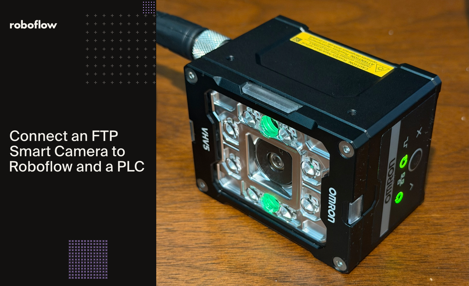
You can add AI defect detection to smart cameras that only send images over FTP or SFTP, like the Omron VHV5. A small Python bridge receives each image, runs it through a Roboflow RF-DETR Workflow that finds scratches and dents on 3D-printed parts, and writes one status word to an Omron NX102 PLC over OPC UA, in about 800 ms per part on a local GPU.
This guide shows how to build a 3D print defect detection system with an FTP camera, Roboflow, and a PLC. The system inspects finished 3D-printed shock towers for scratches and dents, then sends an inspection result to an Omron NX102 controller over OPC UA.
The connection starts with a small Python application called the VHV5 Viewer. An Omron VHV5 barcode reader captures each part in a fixture and uploads its image over FTP or SFTP. The Viewer sends that image to a Roboflow Workflow running in the cloud or locally in a Docker container, then writes the result to the PLC. Operators see the verdict in the Viewer and on indicator lamps at the station.
We’ll walk through the camera setup, defect detection model, Workflow logic, and PLC integration. Along the way, we’ll show how consistent lighting and positioning support inspection, how detections become a compact status word, and how the application reports missing parts, unreadable QR tags, and inference failures.
What Defects Can This System Detect?
This project uses computer vision to detect scratches and dents on finished 3D-printed shock towers. A camera captures each part in a fixed inspection fixture, and a trained Roboflow model locates visible defects in the image. The application converts those detections into a pass/fail result that an Omron PLC uses to control indicator lamps.
The inspection checks for two defect classes:
Scratch: Visible surface marks identified by the model.
Dent: Localized surface damage identified by the model.
The Workflow also checks whether a part is present and whether its QR tag can be read. These checks prevent an empty fixture or an unreadable serial number from being treated as a successful inspection.
Hardware and Software for 3D Print Defect Detection
The project has three layers, and any one can be replaced without touching the other two.
Hardware: Everything sits on one Ethernet switch and one subnet. With inference running locally, no image leaves the site.
Component
Model
Role
Barcode reader
Omron VHV5 (VHV5-F000L050M-SRX-D)
Captures each part and reads the QR tag
Machine controller
Omron NX102-9000
Decodes the result and drives the lamps
I/O units
ID3344 (inputs), NX-OD4256 (outputs)
E-stop and trigger button in, three lamps out
Power supply
S8VK-X09024A
24 VDC
Ethernet switch
W4S1-05D
5 ports, one cable per device
Inference PC
Ryzen 9 3950X, 64 GB RAM, Quadro RTX 4000 (8 GB)
Runs the Viewer app and the Roboflow Inference container
Software: Omron's VHV5 WebLink, a browser tool, configures the camera. The VHV5 Viewer, a custom Python app extended for this project, is the bridge between the camera, Roboflow and the PLC, and it logs every part to CSV.
AI: A Roboflow RF-DETR (opens in a new tab) Small object detection model inside a Roboflow Workflow. The same Workflow runs on the Roboflow Serverless Cloud API or in a Roboflow Inference Docker container on the GPU PC, and the Viewer can send each image to either.
Connect an FTP Camera to Roboflow
Roboflow's camera integrations are built around streams such as RTSP, USB and GigE Vision, and Roboflow doesn't receive images over FTP. The VHV5, like many smart cameras and barcode readers, can upload files into FTP or SFTP servers.
A custom Python block in a Roboflow Workflow can't stand in for that server: blocks run only when the Workflow is called, but something needs to be listening to the camera at all times to get the images.
So the Viewer app plays three roles: an FTP and SFTP server on the camera side, a Roboflow client in the middle, and an OPC UA client on the PLC side.
On the Camera
Two settings in WebLink do the job. The FTP settings (Device → TCP/IP Settings) point at the PC's IP address with a username, and the cycle archive output (Setup → Output) is set to FTP Server. After every cycle, the camera uploads two files: the PNG image and a JSON report with its own result for that cycle.
On the PC
FTP and SFTP in one app. The Viewer runs an FTP server on port 21 and an optional SFTP server on port 22, built on the pyftpdlib and paramiko libraries. SFTP encrypts the transfer and can authenticate with the camera's SSH key: WebLink exports the camera's public key, and the Viewer imports it.
Inspect on arrival, pair before deciding. The image goes to the Workflow the moment it lands. Over FTP the image arrives before the report; over SFTP the report comes first. The Viewer accepts either order and builds the verdict once both halves are in.
One HTTP call per part. The PNG goes to the Workflow as base64 in a single POST to /infer/workflows/{workspace}/{workflow_id}, either on the Roboflow Serverless Cloud API (https://serverless.roboflow.com) or on the local container (http://localhost:9001). Python's standard library is enough.
Never block the upload. Inference runs on a worker thread, never on the FTP thread, so a slow call can't hold up the next part.
OPC UA from the same app. The Viewer is also the OPC UA client to the PLC, built on the asyncua library. It runs on its own background thread, reconnects if the PLC drops, and puts a timeout on every write, so an offline PLC can't stall the camera side. The tags it writes are covered in the OPC UA section below.
The body of the Workflow request is small:
JSON
{ "api_key": "...",
  "inputs": { "image": { "type": "base64", "value": "<png bytes>" } } }
From Image to Verdict
To increase the image consistency, a light box and a fixture were used. Make sure that the lighting is not impacted by external factors, such as shop lights or sunlight. The fixture makes it so that the part is always in the same place, making it easier to train the model and run it. The camera settings are locked in WebLink: exposure at 3000 µs, gain at 50, focus at 300 mm and the strobe at low, so every image matches the training set.
Train a Scratch and Dent Detection Model
The model was trained on 47 labeled images with two classes, Scratch and Dent, split 39 / 5 / 3 for training, validation and testing. Every image was captured with the part in the fixture, exactly as the camera sees it during inspection.
Object detection, not classification. The status word counts defects, so the model has to find where they are and how many.
Augmentation for real variance only. Brightness, slight rotation and noise, but no flips, because the part only loads one way.
Whole parts held out. Six of the 30 printed parts never went into training, which makes them an honest test.
Forty-seven images is enough for a proof of concept, not for a production dataset.
Turning Detections into a Decision with Roboflow Workflows
A model returns boxes; a machine needs a verdict. After the image input, the Workflow runs four blocks:
defect_model: the trained RF-DETR model
defect_filter: a stock block that drops low-confidence boxes, so one noisy box can't fail a good part
robust_qr_reader (custom): reads the QR tag and reports when it can't, because a blank string is never a pass
acceptance_spec (custom): confirms a part is present, counts defects, checks the QR, and packs it all into one status word
Presence is checked first. With nothing in the fixture, "zero scratches and zero dents" is true and meaningless, so the block leaves the scratch and dent bits off and sets the part-missing bit (8). If the QR tag can't be read either, it also sets the QR fault bit, for a total of 9. An empty fixture can never pass.
One Status Word for the PLC
The PLC can't parse JSON; it needs one number. Each fault gets a bit, and the bits add up, so scratch plus dent reads 6:
Value
Meaning
0
Pass
1
QR fault
2
Scratch
4
Dent
8
Part missing
16
Inspection error
Send Inspection Results to an Omron PLC over OPC UA
The VHV5 Viewer is an OPC UA client, and the NX102 hosts the server. Each cycle the app writes seven tags: the verdict, three pass/fail flags, the QR serial, Inspect_StatusWord, and last of all a cycle counter, Vision_Cycle. The counter works as a data-ready signal, so the controller never acts on a half-written result.
Roboflow Workflows include an OPC UA Writer block that can write tags directly. Here the Viewer writes them instead, so when inference fails, something outside the Workflow is still there to tell the PLC.
About twenty lines of structured text on the NX102 decode the word and drive three lamps:
Lamp pattern
Meaning
Chase 1, 2, 3, repeating
Pass
Lamp 1, 2 or 3 solid
QR fault, scratch or dent (several can light)
All three flashing
Part missing
Lamps 1 and 3 alternating
Inspection error
What the Results Show
The Viewer draws each detection on the image with its class and confidence, next to the verdict, the status word and the inference time.
Teaching the System to Say "I Don't Know"
The Workflow has two safeguards built in. After the model runs, any low-confidence results are dropped, and then a simple comparison checks whether the part is even in the fixture before any defects are counted. Putting these safeguards in place increases the reliability of the system. Both of them run inside the Workflow, though. If the Workflow itself times out or fails, neither one gets a chance to report it.
The Workflow sets values 0 through 9. The Viewer app sets 16 on its own when inference times out, errors or returns no status word, and it shows in the app, on the lamps and in the log.
A Workflow that failed to run can't be trusted to announce that it failed to run.
The same applies to the QR tag: an unreadable serial is a fault, not an empty field that slips through.
Edge vs. Cloud: Where to Run Inference
Where it runs
Time
Local GPU (Quadro RTX 4000), trigger to result
~800 ms (inference 590 to 940 ms, typically ~750 ms)
Roboflow Serverless Cloud API, same Workflow
~3.5 s
CPU only
Close to 2 minutes
The local container is roughly four times faster, and the cloud still makes a good fallback. Both server URLs are in the Viewer's settings, so if the GPU box fails, the line switches to the cloud and keeps inspecting, just more slowly.
From Proof of Concept to Production
Scale the model: production images become training data, so 47 becomes 4,700 without a staged photo shoot.
Scale the deployment: more stations share one container, with a versioned Workflow and the same status-word contract.
Scale the integration: send the status word to MES, tied to work order and lot, so containment is bounded to a lot, not a week.
The first improvement to make is the presence check: a trained presence class instead of a brightness threshold.