It’s amazing to watch what AI enables today. In one day, almost anyone can handle the amount of work that fifteen years ago would have required an entire manufacturer’s development department and taken months. I don’t mean AI does the work for you – as you’ll see later, I spent a lot of time shooting down its nonsense. But the shift in what’s achievable for one person over a weekend is enormous.
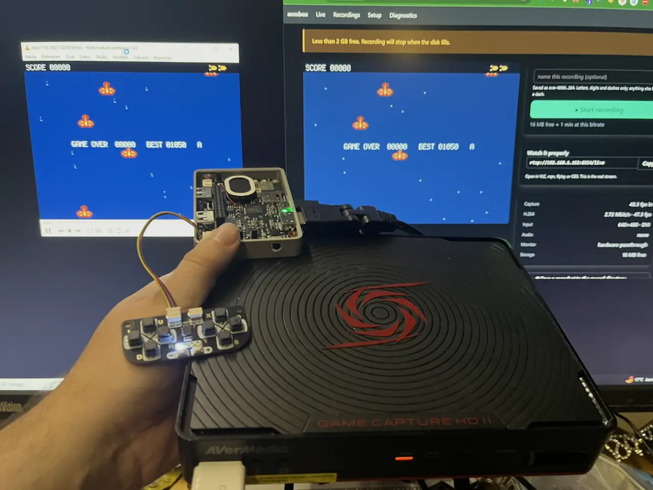
I tried it on a box left over from that era: AVerMedia Game Capture HD II, model C285. Solid piece of hardware – inside sits a Texas Instruments DM368 SoC at 432 MHz, 256 MB RAM, and a hardware H.264 encoder.
At launch it could do sensible things: record to disk, stream straight to YouTube, be controlled from a phone. But the YouTube API has long since vanished, the mobile apps disappeared from the stores, and I lost the remote years ago. Support ended. What remained was working hardware with no usable path to it.
I dusted it off for a specific reason. I’m working on the ** picogame** engine for microcontrollers and needed to capture their video output –
DVI 640×480. I hoped the box could at least handle something that simple, since recording to disk can be triggered by the hardware button.
It couldn’t 😥. The input only supported a very limited set of resolutions and VGA 640×480 wasn’t among them. The box simply rejected the signal.
That was the moment I decided to look inside. I’ll give away the punchline right away because it shows exactly what this whole piece is about: the limitation wasn’t in the hardware. The kernel driver has a table of supported input modes and the 640×480 progressive entry had been there the whole time. You just couldn’t reach it through the vendor app.
What’s inside #
I wanted to know why 640×480 was being reported as a bad resolution – whether it was a hardware or software limit. So I opened the box and looked at what was actually driving it.
| Part fitted | |
|---|---|
| SoC | Texas Instruments DM368ZCE, ARM926EJ-S core @ 432 MHz |
| integrated HDVICP – hardware H.264 coprocessor | |
| ISIF + IPIPE (previewer and resizer) for image processing | |
| Control MCU | Nuvoton NUC100 (Cortex-M0) – I²C master for the whole board |
| HDMI input | ITE IT6604E – HDMI/DVI receiver |
| HDMI output | ITE IT6613E – HDMI transmitter |
| Analog input | TI TVP7002 – component/VGA video decoder |
| RAM | 2× Nanya DDR2, 256 MB total |
| NAND | Winbond W29N01HVS1NA – 1 Gbit SLC, i.e. 128 MB |
| Ethernet PHY | Realtek RTL8201EL – 100 Mbit |
| USB ↔ SATA | Genesys Logic GL830 |
| Bus drivers | several 74LVC244A between the ITE chips and SoC |
| RTC | backed by CR2032 |
| EEPROM | 24C256 (32 kB) on I²C, holds settings and MAC address |
| Audio | two TI TLV320AIC3x codecs |
One thing only became obvious after disassembly: several 74LVC244A drivers sit between the ITE chips and the SoC. That’s physical proof of how the video bus is routed, and it made sense later: the receiver and transmitter pass data over a shared 16-bit bus and the SoC just reads from it. That’s why the monitor can show the picture even without active capture through the SoC.
The NAND holds two complete firmware sets:
mtd0  boot        0x00000000–0x003c0000   3.75 MB
mtd1  params            0x003c0000–0x00400000    256 kB   (U-Boot environment)
mtd2  kernel_fw1        0x00400000–0x00800000      4 MB
mtd3  filesystem_fw1    0x00800000–0x04000000     56 MB
mtd4  kernel_fw2        0x04000000–0x04400000      4 MB
mtd5  filesystem_fw2    0x04400000–0x07c00000     56 MB
mtd6  programer_space   0x07c00000–0x08000000      4 MB   (writable jffs2)
Two banks switched by a single variable in the boot. That turned out to be crucial – one bank stayed as a safety net I could always fall back to while I repeatedly overwrote the other and bricked it several times.
The hardware can do it, so why not? #
The datasheets gave no hint that these chips would have trouble with 640×480. The IT6604 is a standard HDMI/DVI receiver that handles VGA modes without issue. The IPIPE in the DM368 works with widths up to 2176 pixels. 640×480 is a dramatically lighter load than the 1080p the box supports.
So I figured the limit had to be in software – and that the box was probably running some kind of Linux. A quick search confirmed it, and more thoroughly than I had hoped.
Texas Instruments supplied a DVSDK for this family – Digital Video Software Development Kit. It’s not just a driver; it’s a complete toolkit for exactly this kind of device:
codecs-dm365– the H.264 encoder running on the HDVICP** linuxutils**– kernel modulescmemk
(contiguous DMA memory),edmak
,irqk
,dm365mmap
- and most importantly
dvsdk-demos, which includes a demo called
encode
That’s the key. The vendor application in this box is called ** encode** and is started by the init script
. In other words, the commercial product I once bought is a descendant of a Texas Instruments SDK demo – and the name is still there today.
/etc/init.d/encode-demo
The entire SDK is still present on the box in /opt/dvsdk/dm368/
, including the loadmodules_hd.sh
script that loads those kernel modules. The versions match the era: Linux 2.6.32.17-davinci1 kernel built in December 2017 with gcc 4.3.3, U-Boot 2009.03 boot from January 2014.
That changed the job. It was no longer about bypassing a hardware limit – it was about reaching the layer the vendor app was hiding.
The mobile app that no longer exists #
Before digging deeper I tried the simplest thing: what does the box actually offer over the network? It answered on a single port running the API for the mobile app. That app had vanished from the stores, so it was useless on its own.
I managed to find an old APK and decompiled it. The whole protocol came out. It was simple – unencrypted HTTP on port 24170. No authentication, no TLS, no complications. There’s also traffic the other way: the box sends events to the app on TCP port 1516.
I mapped out 117 endpoints in total – pairing with PIN, input switching, starting and stopping recording, emulating remote buttons.
This is where AI first came in. From those findings I had it write a CLI tool and a small web app to control the box. It worked practically on the first try and completely replaced both the lost remote and the dead mobile app. Without touching the firmware I had the box controllable again.
Serial console: first entry inside #
I had control back, but the original problem remained. I hoped that somewhere in the menu – which I could now finally walk through – I’d find a setting that would enable the resolution. No such luck. Nothing like that exists in the menu.
Time to go one level deeper. On the board I found what looked like a UART port. I carefully traced the pins, hooked up a converter, and soon U-Boot appeared on screen (115200 8N1, matching the datasheet).
U-Boot 2009.03-dirty (Jan 14 2014 - 09:44:01)

I2C:   ready
DRAM:  256 MB
NAND:  128 MiB
In:    serial
Out:   serial
Err:   serial
Linux followed, then the vendor app. First snag: the app took over the inputs, so the serial console became useless once the app started.
I could interrupt the boot with CTRL+C and get a login prompt:
|  _  |___ ___ ___ ___   |  _  |___ ___  |_|___ ___| |_
|     |  _| .'| . | . |  |   __|  _| . | | | -_|  _|  _|
|__|__|_| |__,|_  |___|  |__|  |_| |___|_| |___|___|_|
              |___|                    |___|

Arago Project http://arago-project.org dm368-evm

Arago 2011.02 dm368-evm
Arago is the distribution TI shipped for this family – built on OpenEmbedded. And note the hostname: ** dm368-evm**, the name of the development kit. Again, the reference design exactly as it left the chip vendor.
Even that login wasn’t much use – the vendor app started in parallel and ignored the serial input again. The console was taken.
One thing the CTRL+C did reveal, though, and it mattered more than the login itself: it worked. The box really was receiving my characters – the serial line was bidirectional. Keep that in mind; it’ll become a puzzle shortly.
That left one lower layer: getting into U-Boot before Linux even starts. The boot itself offered exactly what I needed:
Hit any key to stop autoboot: 1
Press any key. One-second countdown.
It didn’t respond to keys.
And that’s why it was a real puzzle, not just a wiring mistake, because serial was demonstrably working. Characters were leaving. The boot was just discarding them for some reason.
Downloaded firmware is encrypted #
Before trying to crack the console I of course tried the easier route: download the old firmware the manufacturer once released and dissect it on the bench. No luck.
The files had a readable header:
AVT-CEDxc285WW001.002.0990.0.20.0.32 201710121914 723c8a4f5cacd1cc5a3fabb...
#k_s
2364296
#f_m
16
#f_s
3145752
3145752
...
But everything after that header is encrypted (entropy 8 bits per byte = essentially random data).
That clarified the goal: I had to reach the decrypted state inside the running system. Dumping the flash directly from the chip was off the table – I don’t have the gear for it (it’s parallel flash that would need desoldering, not simple SPI).
Noise on the serial line #
That left the console and the U-Boot that ignored keystrokes. One trick I tried was sending noise to the serial input – just a stream of random data instead of specific key presses.
And it worked 🤯. The screen showed:
DM365 EVM >
Boot prompt!
What that unlocked:
Extended countdown. I set bootdelay
from one second to five so I’d have more time to hit a key next time. Spoiler: it didn’t help, and why is one of the best parts of the whole story – we’ll come back to it.
The prompt itself isn’t the win yet. Worth noting what this U-Boot can and can’t do: the command table has nand
, setenv
, saveenv
, bootm
, dhcp
, tftpboot
– but no usb, fatload or mmc. From U-Boot alone you couldn’t save anything to a USB stick; it could only reach out over the network. The real value of the prompt was elsewhere – it let me
rewrite what gets passed to the kernel at boot. And that’s exactly where the next step lay.
From boot to shell: rewrite bootargs #
The original boot parameters looked like this:
bootargs=mem=97M console=ttyS0,115200n8 quiet root=/dev/mtdblock5 rootfstype=cramfs ro
         video=davincifb:vid0=OFF:vid1=OFF:osd0=1280x720x16,5400K
         dm365_imp.oper_mode=0 davinci_capture.device_type=4
         davinci_enc_mngr.ch0_output=LCD davinci_enc_mngr.ch0_mode=720P-60
bootcmd=nboot 0x80700000 0 0x4000000;bootm
That line revealed a lot:
- the system runs from
– the second bank,
mtdblock5
filesystem_fw2
, - the root filesystem is
cramfs, mounted read-only(so nothing can be overwritten easily), - the kernel gets
97 MB out of 256– the rest is reserved for the codec, - video output is hard-coded to
720p60, - and there are driver names with parameters:
dm365_imp.oper_mode
,davinci_capture.device_type
,davinci_enc_mngr.ch0_output
. Every one of them proved useful later.
All I had to do was append init=/bin/sh
at the end. The vendor app only starts from init scripts – if init never runs, the app never starts, doesn’t steal the serial console, and for the first time I have a real root shell on a running, decrypted system.
From here it was routine: mount a USB stick and dump the NAND partitions one by one with dd
from /dev/mtd*
. Boot, both kernels, both filesystems.
Treasures in the decrypted system #
Now I had the entire filesystem on disk and could poke around at leisure. It paid off three times immediately.
Firmware key
Remember those downloaded .bin
files with exactly 8.0 entropy that wouldn’t unpack? The answer to how to decrypt them sat inside the main encode application in this command:
openssl enc -d -des3 -in /tmp/file.en -out /tmp/file.de -pass pass:Av3rMed1a
That’s 3DES with the password Av3rMed1a – you might spot something in that password 🙂. Now just one command:
openssl enc -d -des3 -md md5 -pass pass:Av3rMed1a -in blob.en -out blob.de
The cipher is symmetric and the readable header is the complete recipe for reassembling the package. The key could even be used to build a custom “official” firmware that the app’s updater would accept. I never needed it though: with a root shell I can just write the modified system straight into the inactive NAND bank and bypass the whole update mechanism.
Root password: DES crypt and half an hour with hashcat
From the decrypted system I pulled /etc/passwd
. The root line:
root:xvaWxZvodd.wU:0:0:root:/home/root:/bin/sh
It’s an ancient DES crypt(3) hash. Hashcat gave it up after roughly half an hour. The password itself would have been useless without a shell – the box doesn’t run any network login service by default. And that’s exactly what came next.
Telnet via a single boot environment variable
telnetd
is present on the box (BusyBox), but it doesn’t start by default. The init script encode-demo
contains this:
var_logswitch=`fw_printenv log_switch | cut -c 12`
if [ "$var_logswitch" == "1" ]; then
    telnetd
fi
Remote access hinges on a single U-Boot variable – log_switch
. It was originally meant to enable debug logging, but as a side effect it also starts telnet. Because the boot environment is persistent (it lives in partition mtd1
), setting it once from the shell with fw_setenv
makes telnet start automatically on every subsequent boot.
Done. Root password from the cracked hash + telnet that starts automatically = full, persistent root access to the box over the network, no serial cable, no bootargs changes on every boot. From this point the box was just a regular little Linux server I could connect to and work on anytime.
Custom firmware – and this is where AI starts working #
Up to this point it was classic reverse engineering: cable, console, dumps, cracked hash. From here the nature of the work changed. I had a decrypted system and root access over the network – time to write my own software and get it onto the box. AI did practically all of this part (Claude Code specifically, on Opus 4.8 / Opus 5 / Fable 5 depending on how deep the details went – and on which of them was refusing to do the risky stuff at the time). AI produced the custom recording application, HTTP and RTSP servers, web interface, build and flashing procedure (with a little steering in the right direction). It wasn’t without pitfalls, but the amount that appeared in essentially one evening would otherwise have meant weeks of work.
Why you can’t just overwrite it
The filesystem is cramfs mounted read-only – we already knew that from bootargs. Nothing can be written to it at runtime; any change means building an entire new image. AI turned that into a reproducible build: it enumerates devices in /dev
from the original cramfs, builds the tree under fakeroot
, and reassembles it with mkfs.cramfs
. The result is an image the kernel mounts exactly like the vendor one – except it contains my application instead of encode
.
Two banks as a safety net
This is where the dual-bank design from the first chapter really paid off. I always flashed custom firmware into the inactive bank while the running system stayed on the other. When a new image failed – and it failed several times – the old bank still booted. That’s priceless during experimentation.
But flashing took fifteen minutes
The catch was that you can’t overwrite the bank the system is currently running from – it’s being read continuously, so erasing it from under the running system bricks the box. You had to boot into the second, vendor bank, overwrite ours from there, then boot back. Two reboots, erase, flash, and time spent in the vendor firmware – about fifteen minutes total.
For one final release that’s fine. But during debugging, when you’re changing one line and want to see the result, fifteen minutes per iteration is a killer. There had to be a better way.
Firmware from a USB stick
The solution was elegant and used something that was already in the box – USB storage. The launcher for the custom firmware checks a connected USB stick every time the application (re)starts. If it finds a binary called avmbox_h264
on the stick, it runs that instead of the one in flash:
for d in /tmp/media/*; do
    if [ -x "$d/avmbox_h264" ]; then OVR="$d/avmbox_h264"; break; fi
done
That turned fifteen minutes into a few seconds: wget
the binary to the stick, call /api/restart
– and the new version is running. Flashing was kept only for baking the final verified version into the permanent image.
Why the box rejected 640×480 #
Now that the custom app was running I could finally return to the original question: why did the box reject that resolution? It really wasn’t about hardware. No part of the chain has trouble with 640×480: the IT6604 receiver locks onto it, the davinci_capture driver knows it, and encoding is handled by FFmpeg on top of the hardware encoder, for which it’s trivial.
The snag was one layer higher – in the vendor app’s policy. encode compares the detected mode against a manually maintained list of allowed standards, and if the mode isn’t on the list the setting fails with exactly that “unsupported resolution” message. It wasn’t a technical limit, just a whitelist that nobody had ever added VGA to (and the UI was hard-coded around 720p anyway).
It could have been fixed by patching the binary, but that would still have left a closed app talking a dead protocol. The cleaner path was our own application: it talks straight to V4L2 and simply takes whatever geometry the driver locked onto – 640×480 just “works”, and in the same step we gained streaming, a web interface, and codec choice.
Battle of the colours: when the guesswork is in the wrong module #
Capture started, but the image was green and shifted down. This is where working with AI showed both its better and worse sides at once 😁.
First the worse. AI generated theory after theory – wrong byte order, swapped colour components, colour-space conversion in the chip – and tried each one blindly. Several rounds, no progress. It was digging in the image pipeline module that looked like the culprit. It wasn’t.
The breakthrough came when I insisted on measurement instead of guesses. AI read the raw frames straight from memory and it turned out the colours were correct on the bus the whole time – the error wasn’t before the chip but further down the pipeline, somewhere other than where we’d been looking. From there it took two small clarifications: one told the chip to treat incoming data as colour (without it everything went green), the second adjusted where the active area starts in the frame (that fixed the vertical shift). Two bits and the picture was right.
AI can generate endless plausible-sounding hypotheses and dutifully test them – but without measurement it just spins in circles. The productive part didn’t start with a better theory; it started when I forced it to stop guessing and start measuring.
Performance: from 3.6 to 60 frames per second #
The first capture version ran at 3.6 frames per second. That’s a slideshow, not game recording. Getting to usable speed went through three bottlenecks, all of them unnecessary memory work.
First, every frame was being JPEG-encoded in software – 270 ms and the CPU at 99 %, even when nobody was watching. I made it run only when a preview was actually needed. Then it turned out the frames sat in uncached memory the CPU reads painfully slowly (~21 MB/s); moving them via the hardware DMA controller cut the same transfer to 3.2 ms and pushed FPS past thirty. The last bottleneck was pixel-format conversion for the hardware encoder – 10.7 ms per frame, almost as much as the entire encode step.
And here came the nicest moment of the whole debug session: the capture hardware can deliver that format directly. The only thing preventing it was a typo in parameter parsing – the -E
switch was accidentally disabling -N
. So: a bug in code AI had written itself – and it then spent real effort laboriously optimising a conversion that never needed to happen at all 🤦. After the fix the conversion dropped to zero and the frame rate finally landed where I wanted it.
Web interface #
The capture chain was now running fast and with the right image. All that remained was making it controllable. The vendor app was driven by remote and phone, both gone. So I had a web UI written using Bulma and Alpine.js – both pulled from CDN (I like that combination with microcontrollers).
The interface has four pages: live preview, recordings, settings, and diagnostics. Almost every decision in the UI stems from one fact: on such a slow SoC every request costs something – a single status poll
means several I²C reads through the MCU and one config write erases a block in jffs2. So a single timer owns the state (and stops on an inactive tab) and setting changes are sent in batches.
The mystery of the “U” key #
Time to pay the debt from the introduction. Remember the countdown that ignored keystrokes?
Hit any key to stop autoboot: 5
Yet no “any” key worked even though serial was definitely working. I suspected from the start it wouldn’t be any key but a specific one, and I repeatedly asked for the U-Boot code itself to be examined. AI kept insisting it had looked in detail and that any key really should work. It didn’t.
So I had it locate the exact code in the disassembly, and at first glance it was obvious – and AI immediately understood its mistake:
333b40:  bl    0x330c50         ; getc()  - read pressed character
333b44:  and   r3, r0, #255     ; r3 = char & 0xFF
333b48:  cmp   r3, #85          ; ← compare with 0x55 = 'U'
333b54:  bne   0x333b68         ; not 'U'? → ignore and keep counting
333b58:  mov   r5, #1           ; is 'U'? → abort autoboot
333b5c:  mov   r4, #0           ;           and drop to shell
That cmp r3, #85
is the whole story. 85 is 0x55
, and 0x55
in ASCII is uppercase ** U**. It doesn’t wait for any key – it waits specifically for this character. Someone had just left the original default message in place. Even after several requests for a deep check, AI stopped at finding that message and treated it as truth without looking further…
What’s interesting about this episode is how simple it ultimately was – and how long it took. The instruction wasn’t hidden anywhere. It’s a single comparison in a clearly named abortboot
function you can examine in the disassembly in a few minutes…
Where AI struggled #
I promised at the start that it would also be clear where AI stumbled – and I spent plenty of time shooting down nonsense. The patterns repeated:
Trusts the printed message more than the code. That treacherousU
key…; another time a naïve scanner “counted” key frames that weren’t in the file at all.Builds a principle from a single bug. It repeatedly claimed that simultaneous passthrough and recording “isn’t possible” – when it was actually a side effect of its own command, not a property of the device. It even baked that into the API and comments as fact.Invents evidence and believes it. It “proved” the hypothesis that the vendor app rewrites bootargs with a dump it had fabricated earlier – then wrote that into persistent memory as fact.Harms what it’s working on. Several box crashes were self-inflicted – blind probing through the MCU, flooding the system with hundreds of shells (twice it ran out of memory), or akill -9
that took down the network.
On the other hand, those same capabilities handled an enormous amount of correct, tedious work and almost always found the bug once I named it and pointed the effort in the right direction.
What the box can do today #
From a black box tied to services that no longer exist, it became an open network capture box – and it can do more than on the day I bought it. Part of the work was getting the original functions back on our own software. Mainly simultaneous picture on the monitor and recording via the hardware path receiver → transmitter (the original could do that too; it just took effort to get it working on custom firmware). But there’s plenty of genuinely new stuff:
Live RTSP stream over the network– the key feature for me. The original could only push to YouTube. Now I have a universal H.264 stream over the network into OBS, VLC or ffmpeg (and MJPEG straight into a browser).Any resolution– from the 640×480 the vendor blocked and which started the whole project, up to 1080p. The latter required reshuffling the codec-reserved area in memory and freeing ~58 MB inside it.Recording with all the trimmings– Matroska container with proper timing, optional bitrate and frame rate.** Modern web interfaceinstead of the vanished mobile app. 60 fps at 640×480**where it started at an unusable 3.6.
And because it’s now just a regular little Linux server with our own software, this isn’t a final state – it’s a foundation you can keep building on.
Final thoughts #
I started with a box most people would have thrown away: unsupported, tied to a dead cloud, no remote, refusing the one thing I asked of it. I ended with an open device that doesn’t depend on anyone else’s service.
I don’t want to claim “AI did it.” The division of labour was pretty clear. Classic hardware reverse engineering – cable, console, measurement, random entry into the boot – was on me. Once the data was out, though, AI took over the vast majority of the actual work: firmware analysis, decryption key, the entire custom application, servers, web interface, and build. The volume of code and analysis that appeared in a few evenings would once have meant weeks. You just have to remember that a human still needs to be in the loop and understand the tech enough to steer AI’s token-burning hunger in the right direction.